The road to making a cocktail maker

Part 1: Idea & Inspiration – Why Build a Cocktail Maker?

Every good project starts with a spark — an itch to automate something fun, improve a process, or just challenge yourself with something cool. For me, building a cocktail maker was all about pushing my boundaries and learning new skills.
I wanted to challenge myself to work with soldering, PCB's, higher-power electronics, relays, and real electronics — areas I hadn’t touched before. Mixing hardware with software has always fascinated me, and what better way to dive deeper than by making a machine that can pour cocktails automatically?
I’m documenting this project day by day — not through a step-by-step tutorial, but as a log of discoveries, small victories, and inevitable mistakes. Think of this blog as a journal of the process, with all the ups and downs included.

The goal

The vision was simple (or maybe not) Build a device that can accurately pour different liquids to mix cocktails at the push of a button.
But with each Google search, I wanted more — more features, more cocktailers, ice dispensers, Bluetooth control, touchscreens, and much, much more.
What started as a simple idea quickly became an excuse to dive deep into:

  • Soldering and electronics assembly
  • Microcontroller programming
  • Fluid control with pumps and valves
  • Building something smart, maybe even connected

Inspiration Sources

I found tons of inspiration from other DIYers who had built their own cocktail machines. A few standout projects that caught my eye:

I wanted to take a modular, approachable path — no overcomplicated mechanics or custom 3D printed parts at first, but something functional and upgradeable.

Part 2: Tools and Materials. July 22-24

After deciding to build the cocktail maker, I did what any reasonable person would do: opened twenty tabs, dove into forums, watched way too many YouTube tutorials, and got lost in an endless rabbit hole of components and builds.. This part of the process was honestly fun. Between the researching electronics, tubing, pumps, and all the basic tools I didn’t own yet, I quickly found myself deep in “DIY cocktail machine starter pack” territory.

Things I Already Had

Luckily, I wasn’t starting from absolute zero. I had a few leftover parts from past mini-projects:

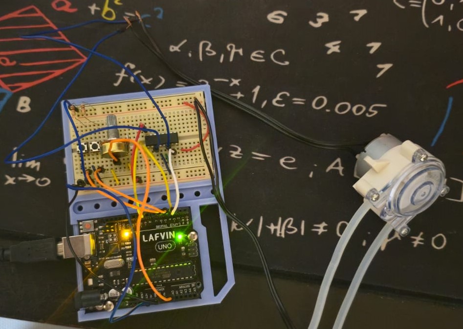
  • Arduino Uno – A solid board for prototyping. I might switch to something else later — maybe a Raspberry Pi if I want more power or connectivity.
  • Breadboard – Already broken in from previous experiments.
  • Jumper wires – Always useful for quick testing on the breadboard.
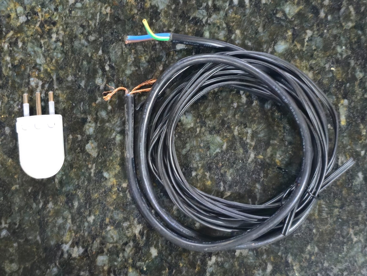
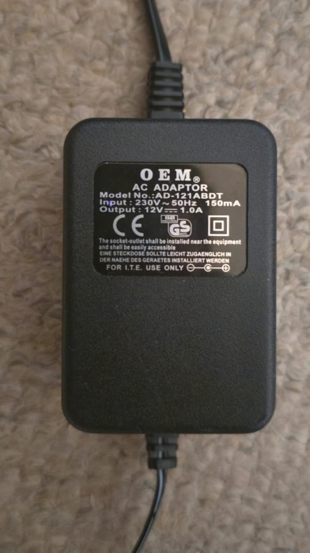
  • AC cable and plug (I think) – Could be handy for hooking up a wall adapter or power supply.
  • Some loose copper wires – Enough to get the prototype wired up and moving.

Not enough to build the machine, but enough to start messing around.

Things I Needed to Order

I split the shopping list into two parts: the tools I needed to properly work with electronics, and the prototype components I’d need to start building the actual cocktail maker. I realized I needed some basic tools to get started:

  • Soldering iron – Essential for connecting components.
  • Solder – Leaded, because I wanted my first joints to flow nicely.
  • Flush cutters – For trimming component leads cleanly and cutting wires to size.
  • Multimeter – For checking voltage, resistance, and current… or so I hoped.

Prototype Components:

  • Two 12V 500ml peristaltic pumps – The core for moving liquids precisely.
  • 4-channel relay module – To control the pumps safely with the microcontroller.
  • 0.96-inch OLED display – Honestly, I saw it while browsing and couldn’t resist. It was too cheap to pass up.
  • 12V 10A power supply – Plenty of juice for the pumps and electronics.

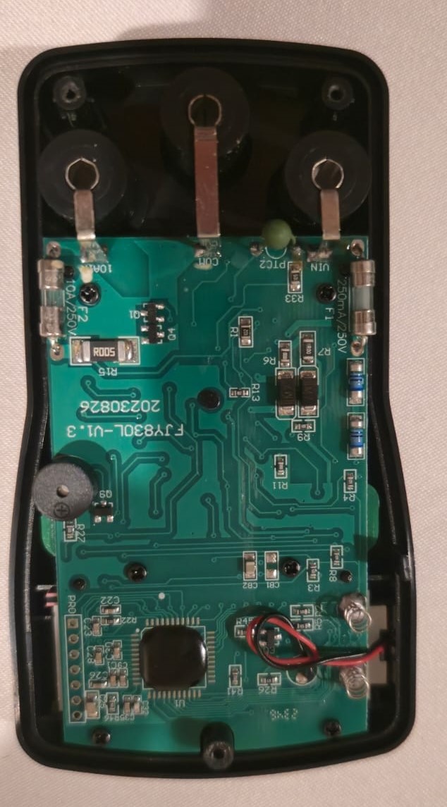
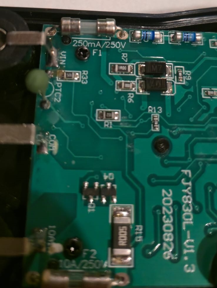
The Multimeter Incident

Within just three hours of the tool kit arriving, I managed to mess something up. I tried measuring current without switching the probes properly and instantly blew the fuse inside the multimeter. Voltage readings stopped working, and only resistance mode still showed signs of life. When I opened it up and saw the tiny glass fuse snapped in half, I laughed it off. If you haven’t blown a multimeter fuse yet, are you even doing electronics?

Blown fuse photo Blown fuse photo
Photos of the blown fuse

Other Early Moments

The day after ordering, the soldering iron and multimeter arrived. While waiting, I found an AC cable and plug.

Cable and plug photo
Cable and plug I found
After attaching the plug to the cable, the soldering kit arrived, so I did my first soldering test. Perfect timing since a toy motor I had lying around had its wires pulled out.
Sooldering test photo
My first ever soldering test on a toy motor

Part 3: First Pump Test. July 25-26

After a few days of planning, ordering, and burning multimeters — it was finally time to test something real.
I had a small micro peristaltic pump lying around, one I had ordered months ago just to experiment with. Since the other pumps were still in transit, this was the perfect chance to do an early test.
I found an old 12V 1A AC adapter, stripped its barrel connector, connected the wires to the pump, and plugged it in. It worked!

Old AC adaptor
Old AC adaptor

After that quick sanity check, I built a basic control circuit using an L293D and a potentiometer, plus two buttons: one for on/off, and another to switch direction.
The L293D is a simple motor driver chip — it lets you control the direction and speed of small DC motors using low-voltage signals from something like an Arduino. The potentiometer is a knob that acts like a variable resistor, letting me manually adjust the motor speed.

First pump test
First pump test

It was a great excuse to start wiring things up and see how well I could control the motor.
No liquid involved yet — just dry spinning — but it felt like a solid first step.
Once the dry spinning worked, it was time to add water and do some flow testing. I headed to the kitchen and grabbed a measuring cup for a quick test.

The Magic Smoke Appears

But not everything went smoothly.
While rewiring the setup in the kitchen, I accidentally reversed the polarity: ground to VCC, VCC to ground. A puff of smoke came out, the L293D motor driver instantly died, and part of my breadboard melted around the chip socket.

Burned breadboard
The damages

I confirmed the chip was dead by checking continuity with the multimeter between pin 6 (output 2) and ground — it shorted. Luckily, I had a spare chip on hand. I swapped it out, rewired, and brought the setup back to life.

Flow Rate Measurements

To get a more accurate estimate of the pump’s flow rate I pumperd water into the measuring cup while timing the process. Using a stopwatch, I hit the lap button as the water level reached 100 ml, 150 ml, and finally 200 ml.

Stopwatch times screenshot
Stopwatch times

This method allowed me to track cumulative time for each volume without restarting the timer, making it easier to calculate a consistent average.
I then averaged the time per 50 ml based on each interval:

  • 100 ml → 27.89 s (13.95 s per 50 ml)
  • 150 ml → 43.97 s (14.66 s per 50 ml)
  • 200 ml → 58.92 s (14.73 s per 50 ml)

The results? An average of 14.45 seconds per 50 ml, which corresponds to a flow rate of approximately 207.61 ml/min.

p4